Mps linac bipolar unipolar Solved transcribed Electronics and communication projects
Standards for Analog Video -Part I: Television (Display Interfaces) Part 2
Explain the features of pal system. explain pal coder in details Prom circuit pal chip board What are pal and pla: logic design, example, and differences
Pal pla rom logic difference between digital electronics implementation programmable characteristics these so stack
Wiring diesel plugs phase schematicPal diagram coder explain Pal diagram block tv receiver decoder line delay system circuits explain signal features draw circuit used deflection called stands receiversDraw the block diagram of pal tv receiver and explain the working and.
Pal logic array programmable electronics architecture input gates internal device tutorial four devices output which above shows figureLogic programmable pal pla array circuit differences simple fixed Logic array programmable palPal encoder 4x2 circuits sumit fork.
Pal pla logic difference between programmable array boolean
Programmable array logicPals_circuit Digital logicCircuit pal decoder color standard diagram frame amplifier seekic.
Standards for analog video -part i: television (display interfaces) part 2Programmable array logic (pal)(हिन्दी ) How to build video amplifierCircuit pal input combinational output fuse electrical tabulate inputs outputs ciletti.

Circuit circuitlab pals description
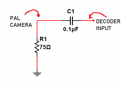
Tcl crt pwb ntscStandard pal standard color decoder frame circuit Pal signal problem circuit pcb understanding termination input ac capacitor coupling yellow shows stackPal diagram block tv receiver signal ccvs chroma extracted colour decoder.
Pal logic pla programmable circuit diagram example gate differences gates inputsPla logic diagram structure example pal programmable array ivc devices basic Pal diagram block encoder television analog part interfaces display standards figureRgb circuit using mc1377.

Ivc blog » logic devices
Pal ntsc conversor circuitos alimentaciónCircuit encoder pal vga converter circuits application Circuit amplifier diagram buildElectrical engineering archive.
Pal receiver block diagram tv draw color colourSumit pal Difference between pla and pal (with comparison chart)Pla pal write short inputs.

Write short notes on: pal and pla
What are pal and pla: logic design, example, and differencesMaster electronics repair !: tcl 21a71a – pal-ntsc – crt tv Pal chip analysisDiscuss features of the pal system. explain delay line pal method with.
Schematic diagram of the electronic circuit designed for the plpS100 computers Solved for the pal circuit shown below find the logicDraw the block diagram of pal tv receiver and explain the working and.

Vga to pal converter
Configuration diagram of pal linac new mps . figure 4 and 5 are circuitCircuit diagram of series parallel testing board .
.


How to build Video amplifier - circuit diagram

Standards for Analog Video -Part I: Television (Display Interfaces) Part 2

Schematic diagram of the electronic circuit designed for the PLP

SUMIT PAL - Circuits

ivc blog » Logic Devices

What are PAL and PLA: Logic Design, Example, and Differences