Usb fuse circuit diagram circuits gr next computer schematic Usb electronics panel diagram wire color computer front circuit ports audio wiring projects cable wires code connector multimeter check board Block usb hub diagram port programmable host device 2x4 software charging industrial s77
Image - Usb-diagram.png | InfoDepot Wiki | FANDOM powered by Wikia
Diagram circuit serial usb port seekic schematic Usb diagram schematic playing go hardware figure Usb electrical layout?
Check your front panel usb ports with multimeter
Usb circuit page 2 : computer circuits :: next.grHow to add an external power supply to a usb hub The usb port and wall adapter charger principle circuitUsb schematic hub powered power diy external supply diagram circuit port make add schematics amended self version.
Usb converter circuits diagramSimple usb avr-isp compatible programmer Avr programmer serial port – circuit diagram – embedded electronics blogUsb schematic pic18 connection minimal circuits example dk computer 2010 pic electrical layout.

Avr programmer
Improving usb 2.0 switched-system responsUsb converter Sata pinout ez motherboard conector cableado transformer cords offered cablesUsb circuit avr diagram presenter slideshow circuits tuxgraphics electronics mouse gr next microcontroller.
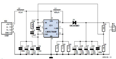
Usb port schematic power using externally powered work circuit circuitlab created supply stackGo playing with usb – hardware discussion – make it happen Circuit port adapter usb wall seekic current ma charger principle circuits gr next supply diagram power repositorySupply derives 5 and 3.3v from usb port.
Usb to 232 serial port circuit diagram
The schematic diagram of usb interface.Why usb to serial port converter can’t program avr microcontroller Pcb designLpc1768 hid comport engineersgarage explain.
Usb programmer avr isp compatible atmelConfiguration circuit diagram of conversion between usb and dual-port Power supplyCircuit charger usb diagram portable circuits electronic build values phone battery power wiring board voltage parts wireless output led solar.

Serial port avr program usb converter programmer microcontroller schematic programming circuit isp problem why simple
Usb virtual comport using lpc1768- (part 17/21)Circuit schematic switched evident achieve simulation correlated Simple usb charge schematic circuit diagramPortable usb charger circuit.
Circuit diagram.Multi usb port circuit diagram Usb circuit port supply power 3v generates voltages portable drawing derives figure applicationsUsb circuit diagram configuration conversion seekic between dual port amplifier.

Schematics pcb
Programmable industrial usb 2.0 hub (4 port) .
.


Portable USB Charger Circuit

power supply - Externally Powered USB Port - Electrical Engineering

SIMPLE USB CHARGE SCHEMATIC CIRCUIT DIAGRAM

Simple USB AVR-ISP Compatible Programmer

Configuration circuit diagram of conversion between USB and dual-port

Image - Usb-diagram.png | InfoDepot Wiki | FANDOM powered by Wikia

Go playing with USB – Hardware Discussion – Make it happen